Design Fifth Order Hairpin Filter. The next step of the filter design is to find the dimensions of coupled microstrip lines that exhibit the desired even- and odd mode impedances.

Pdf Design And Analysis Of A Bandpass Hairpin Filter
A 37 to 42 GHz hairpin filter This filter was designed for a flat response over the 37 to 42 GHz band with low inser- tion loss and return loss better than 16 dB across the band.
. 1 The first step is to select an appropriate low pass prototype. FilterResonatorOffset 0e-3 3e-3 5e-3. The filter circuit which you just designed is in the clipboard and ready to paste into the schematic window.
The response of the proposed filter is shown in fig4. Hence the hairpin bandpass filter is capable of passing the fre-quencies between range 3910 GHz and 4436 GHz and re-jects all other frequencies. FilterFeedOffset 2 filterFeedOffset 2 5e-3.
The filters application is image rejection at the input of a synthesized block downconverter. Filters are compact structures. The simulation results of the filter reach the design goals.
The hairpin filter was designed and simulated using Agilent ADS 13 1 with planar EM analysis using Sonnet Lite 2. You can also shift the resonators and the feeds using the ResonatorOffset and FeedOffset properties of filterHairpin. For a single microstrip line Design and simulation of hairpin band pass filter for.
This application note illustrates a design flow to on a hairpin bandpass filter BPF with a target center frequency of 58GHz. Hpfilt designfilterHairpin18e9FBW10FilterType Chebyshev. Change the ResonatorOffset and FeedOffset and visualize it.
A hairpin filter was designed for a maximally flat response with the 3 dB passband edge frequencies at 2 GHz and 22 GHz respectively. Electronic filters are circuits which remove unwanted frequency components from the signal to enhance wanted ones. Tuning using the Optimization Assistant yielded a value of Delta -41682 mil.
Filter Design For my simple and cheap multiband transverters 5 like the one in Figure 2 I made printed hairpin filters for a number of frequencies. The concept of hairpin filter is same as parallel coupled half wavelength resonator filters. 2 The choice of type of response including pass band ripple order of filter and number of reactive elements will depends on the required specifications.
Table 2 gives a comparison be-tween different research works. Ifilter can be opened in wizard branch in project tab in AWR. Schematic of the microstrip hairpin.
I did the initial design using the Planar EM simulator in Ansoft Designer not included in the free version then. Press CTRL-V or go to the Edit menu and click Paste. Align the schematic diagram as you wish and click the left mouse button.
106 APPLIED MICROWAVE WIRELESS Figure 1. This video shows on how to simulation of coupled line bandpass filter by using ADS software. The advantage of hairpin filter over end coupled and parallel coupled microstrip is its low space utilization.
U can use ifilter in AWR to design a hairpin. This flow combines yield analysis in Cadence AWR Microwave Office software practical topologies synthesized by Cadence AWR iFilter filter synthesis wizard and design validation using the Cadence AWR AXIEM 3D planar electromagnetic EM. First you select filter typeBPFLPF then select filter realization typeMicrostrip stripline.
In figure 3 the S parameter curves are S11 is the return loss or reflection loss and S21 is the insertion loss. The hairpin bandpass filter as the centre frequency 24 GHz and the upper cut-off frequency is 156 GHz and lower cut-off frequency is 253 GHz and the Bandwidth is 09 GHz. The initial design was entered by schematic cap-ture in the Serenade desktop shown in Figure 1 using Harmonicas microstrip distributed ele-ments library.
See attached pic That s very easy to use. Table 1 shows the design specification of bandpass filter. Abstract In this paper Hairpin Bandpass Filter HPBF is designed simulated and fabricated at two 5G low-frequency bands.
Needed for accurate filter design are not available in the free version. The circuit and its relevant S-parameter simulation is ready for simulation. First calculate microstrip shape ratios wd s.
Also the hairpin design is simple. Hairpin filter topology was used to provide a bandpass response centered at 26 GHz with a 3 dB bandwidth of approximate-ly 280 MHz. Then it can relate coupled line ratios to single line ratios.
DESIGN OF THE HAIRPIN BAND PASS FILTER A The design of band pass filter involves two main steps. This filter will be a part of our 5G narrowband Ultra Wide Band UWB reconfigurable antenna project that plays a significant role in the recent wireless networks such as Cognitive Radios CRs. In hairpin filter space is saved by folding the resonator which is half wavelength long.
37 GHz- 42 GHz and 5975 GHz-7125 GHz. The coupler used a design-rule-based transformation starting from an. The hairpin topology is a microstrip band-.
B Filter Design Specification- 1 Center. You can see the help about ifilter. Coupled line transformer inputs were used.
Design a Hairpin filter with a Chebyshev response at 18 GHz and a fractional bandwidth of 10 percent. The design required 4 coupled sections.

Hpfilter Hairpin Filter Ads 2009 Keysight Knowledge Center
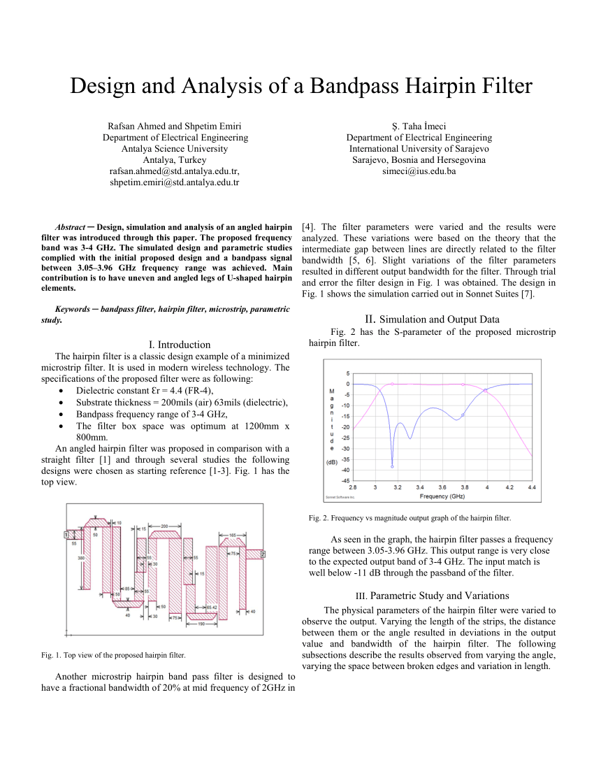
Pdf Design And Analysis Of A Bandpass Hairpin Filter

Hairpin Rf Filters Generator And Measurements Youtube
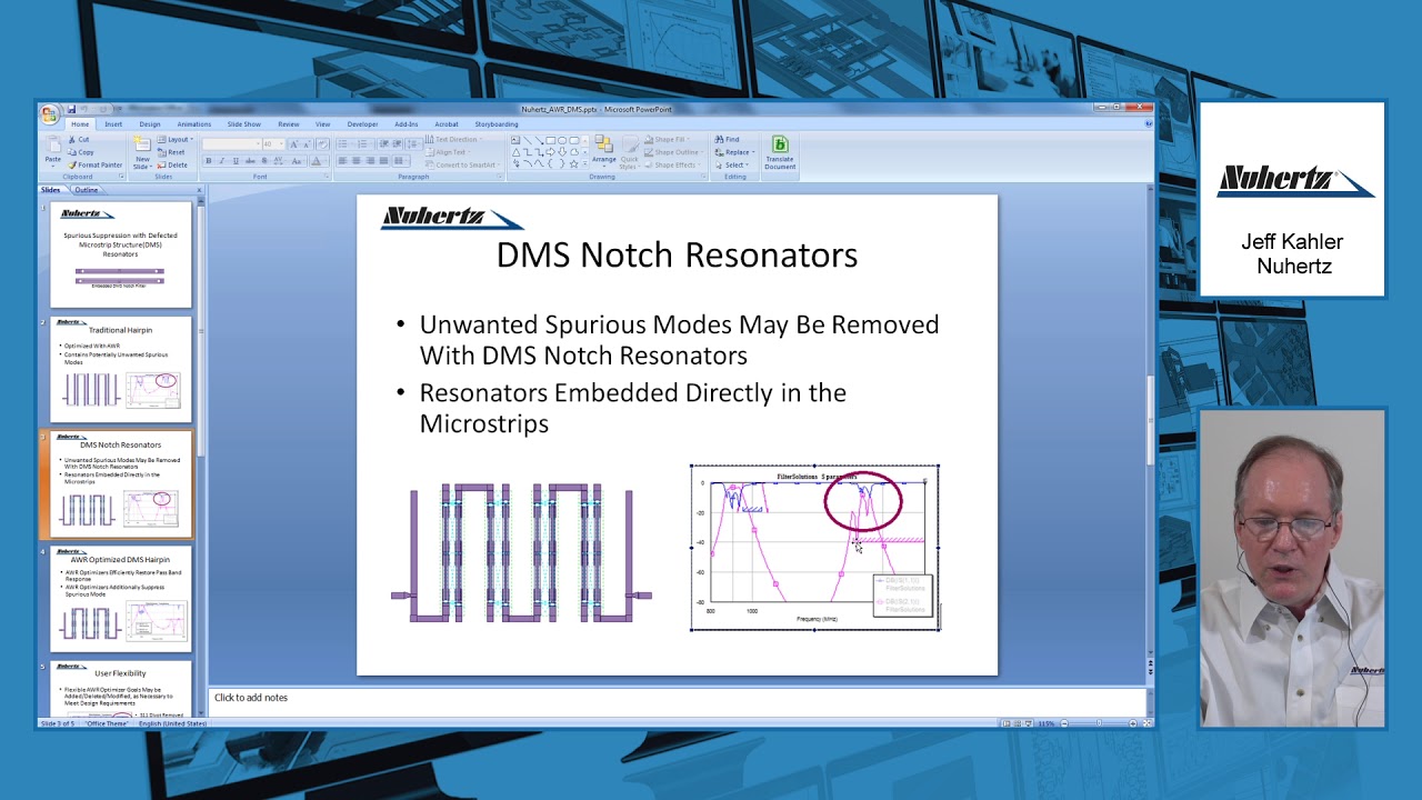
Design Example Nuhertz On Dms Hairpin Filter Youtube
2
2
2

Hairpin Micro Strip Line Band Pass Filter Reflectionless Filter Design Simulation Results In Cst Youtube
0 comments
Post a Comment